Checking parts of the KE-Motronic injection system – Audi 80
The drawings show the location of individual parts. The principles of operation of some parts will be discussed below.
Fuel pump
The fuel pump is checked as described on the page about K-Jetronic injection system.
The descriptions apply to the parts shown in the figure 2.229.
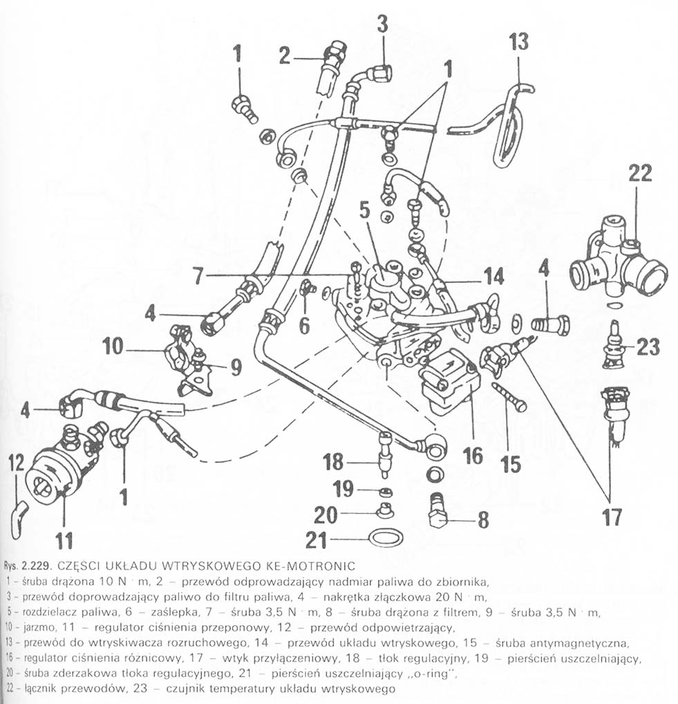
■ Fuel line (2) excess fuel returns to the tank.
■ The supply lines are connected to the fuel filter, which ensures the supply of filtered fuel to the injection device.
■ Union nut (4) to wind with your fingers, then tighten to torque 20 Nm.
■ If the screw (7) it is loose, brush with shellac before tightening (natural resin).
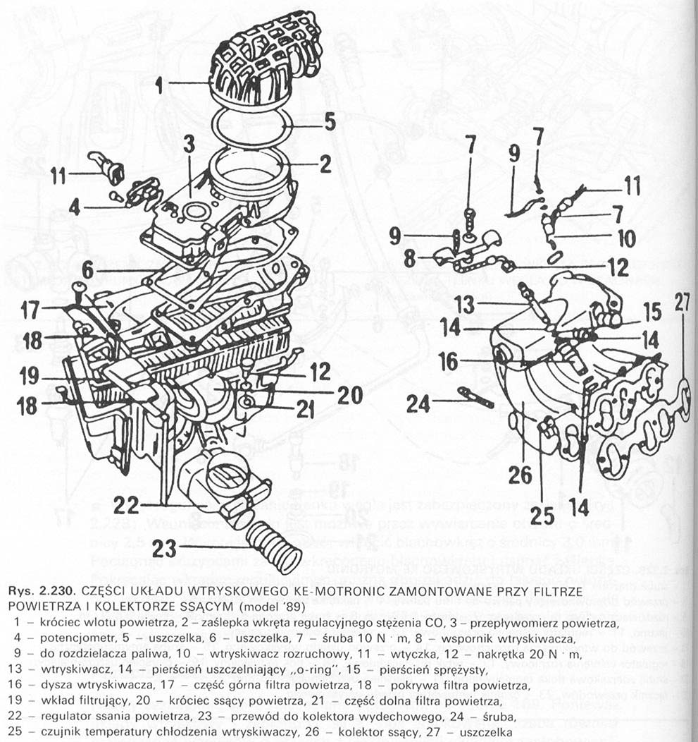
■ Cable (13) it is connected to the starter injector (10, lynx. 2.230).
■ Cable (14, lynx. 2.229) it is connected to the injector (13, lynx. 2.230).
■ Before disconnecting the plug (17, lynx. 2.229) squeeze the wire clamp.
■ Piston or adjuster (18) together with the lever must be adjusted at a workshop.
The following notices apply to the parts shown in the illustrations 2.230 i 2.231.
■ Cover cap (2, lynx. 2.230 the 7, lynx. 2.231) covers the CO concentration adjustment screw in the exhaust gas. Because the change of the screw position is related to the control current intensity, there is no need to remove the cap.
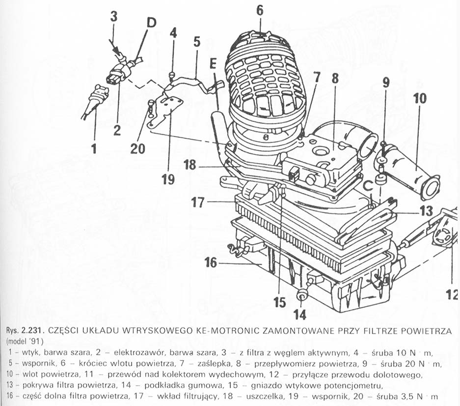
■ Air flow meter (3, lynx. 2.230 the 8, lynx. 2.231) is equipped with a damper, which is visible after removing the air filter. In the event of engine power fluctuations, the damper can be checked as follows:
– disconnect the center ignition wire from the distributor cap (model 89) or remove the three-pin plug from the coil (model 91) and run the starter on 10 seconds; lift the control lever, including the damper; the lever should provide equal resistance in the entire range of the working stroke;
– move the lever down quickly; replace the flow meter if there is any resistance.
■ The potentiometer is factory set. The screws are sealed and should not be unscrewed.
■ The filter mesh must be installed with the convex side facing up.
■ Connect the hose to the fuel manifold (Look 9, lynx. 2.230).
■ Starting injector (10) checked by a workshop.
■ Cable (23) connect to the exhaust manifold.
The following notes apply to the parts shown in the illustration 2.232.
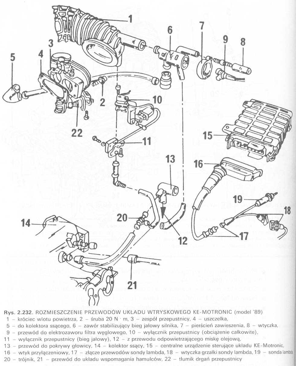
■ The throttle position adjustment screw on the throttle valve assembly (3) factory set. The throttle position should not be changed.
■ Replace the gasket (4) each time the throttle housing is removed.
■ The throttle position sensor informs the central control device of the throttle position at full engine load. A protractor and an electric gauge are used to measure the angular position of the throttle. Measurements can be performed by a service station equipped with appropriate measuring devices. This also applies to the throttle sensor in the idle position.
■ Central control device (15) regulates the operation of the injection system, lambda sensors, and the ignition system and engine electronics. The device is located on the right side of the engine compartment between the bulkhead and the air duct.
■ When disconnecting the plug (16) the ignition should be turned off from the device. The plug is secured with a clamp against unintentional disconnection.
■ Throttle damper (22) slows down the throttle. The muffler must be adjusted in this way, that the gap between the push rod and the lever is 1.5 ± 0.5 mm with the throttle closed.
The following notes apply to the drawing 2.233.
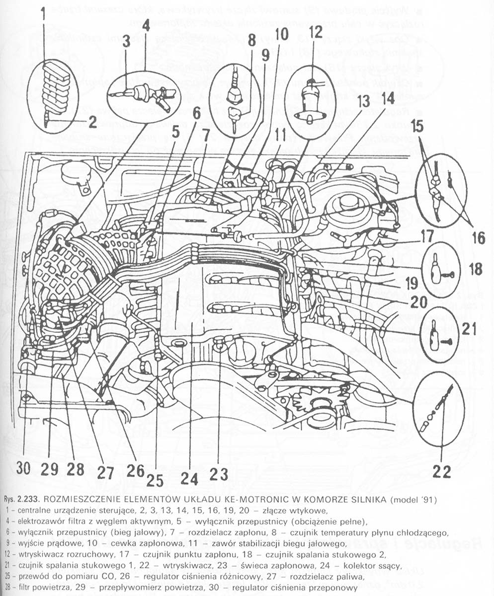
■ The central injection and ignition control unit is located between the transverse plate in the front passenger's legs and the air intake duct.
■ Connector plug (2) can only be removed and connected with the ignition switched off.
■ Temperature sensor (8) provides information about the engine temperature to the injection and ignition systems.