Audi diagnosis 80 crew
I promised, that in time I will describe the diagnostics on these engines.
Description of measurement groups
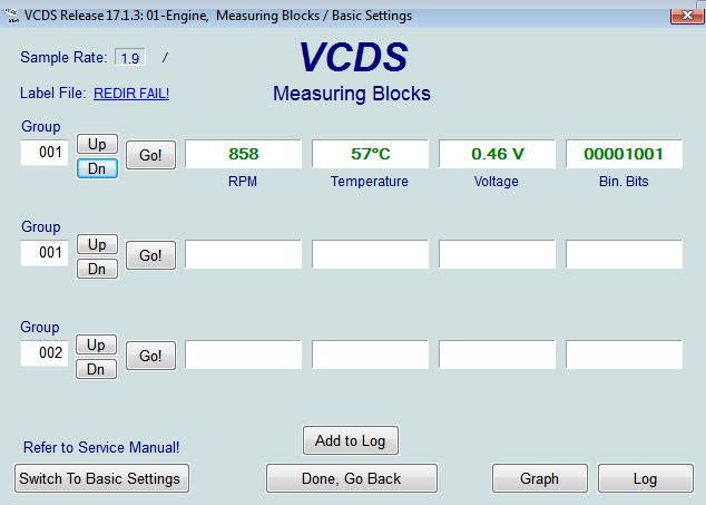
Group 1
1 block – Engine revolutions
2 block – Engine temperature read from the blue sensor
3 block – Lambda probe voltage
4 block – I'm not sure but it seems to me, that it is an error-readiness state
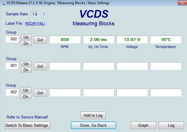
Group 2
1 block – Engine revolutions
2 block – Injection time
3 block – Battery voltage
4 block – boy – (intake air temperature) inlet air temperature
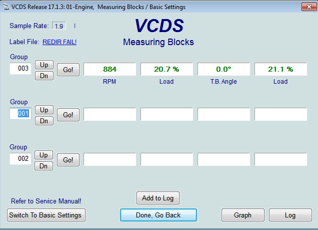
Group 3
1 block – Engine revolutions
2 block – Engine load read from the flow meter
3 block – Throttle position angle
4 block – Calculated engine load
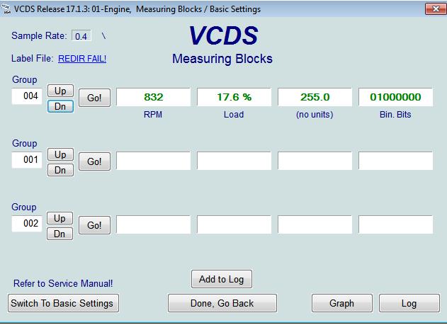
Group 4
1 block – Engine revolutions
2 block – Display from the flow meter
3 block – I do not know
4 block – I do not know
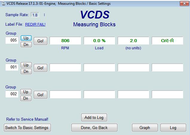
Group 5
1 block – Engine revolutions
2 block – I do not know, I keep showing up 0%
3 block – Dynamic ignition angle
4 block – LACK
1. Stepper motor diagnostics
Connect the diagnostic cable to the OBD1 socket, we run VCDS.
We enter in 01 – engine (01 – Engine), then 03 – Executive tests (03 – Output tests)
We can check the following items
1 – Relay J17 – fuel pump relay
2 – Stepper motor
3 – EVAP valve – tank vent valve
The order was given not accidentally.
For stepper motor diagnostics it is best to remove it (but do not detach the ankle). Then perform the test and observe whether the piston rod in the motor moves freely.
2. Engine temperature sensor diagnostics (blue sensor)
Most often, when it is damaged, it will show -40ºC, but it happens that the sensor is cheating. Then it is best to warm up the engine and check the sensor reading. It should be around 90ºC
The indications are visible in the group 1 block 2.
3. TPS diagnostics (throttle position sensor) throttle position sensor.
The indications are visible in the group 3 block 3.
Slowly push the gas in and check, that at some point the indication:
– does not decrease
– stands still
– is equal to 0
At idle, without touching the gas, the TPS reading should be 0-2 °. In newer digifants it is possible to adapt TPS via VCDS.
4. Lambda probe diagnostics
Display visible in the group 1 block 3.
If the lambda is damaged, the indications most often do not change and are equal to about 0.46V. It is easy to diagnose.
The probe should only be diagnosed when the engine is warm! We diagnose through observation, if the indications change as a result of changes in load and RPM.
If the value does not change, the lambda probe is damaged, but before that, you should check the fuse from the probe heater.
5. IAT diagnostics (intake air temperature) inlet temperature sensor.
Group 2 block 4
Compare the indicated value with the ambient temperature. Of course there will always be a difference but not a big one.
6. Indications from the flow meter
Group 4 block 2
We check the flow meter in the same way as the TPS but manually move the flow meter flap.
At idle, the value should be equal 14-19% (values selected according to experience)
The work of ABK
The lambda probe is damaged, or more precisely, it is missing 
The car is being worked on. This beautiful red toilet seat is not my xD patent
Author: Maciej Soszynski – Source Facebook