Keihin II carburetor repair
 In the drawings 2.169, 2.170 i 2.171 shows the carburetor in parts.
When repairing the carburetor, follow the instructions on the page 136. The carburetor can be disassembled in the following order.
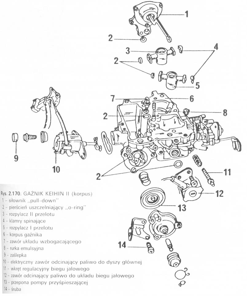
■ Remove the split pins (4, lynx. 2.169). of the rod ends (6), then remove all parts attached to the pull rod. Remove the screws (7) and remove the carburetor cover with the gasket.
■ Unscrew the seat of the needle valve (14) from the float chamber cover and remove the valve needle (15).
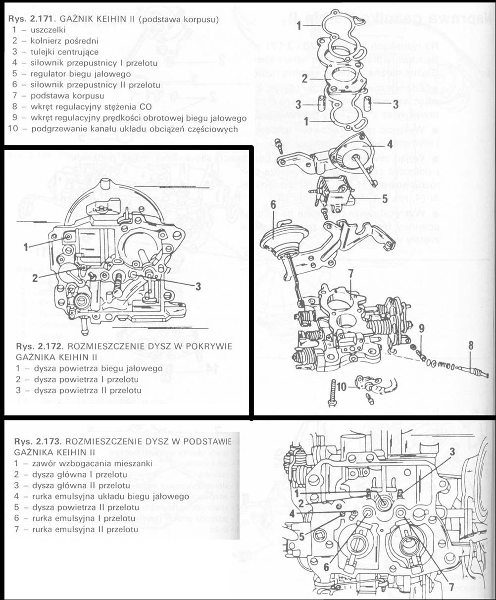
■ Remove the cotter pins from the diaphragm rods of the three cylinders, remove the washers and disconnect the tie rods. The diaphragms belong to the pull-down actuator” boot device (1, lynx. 2.1 70), to the 1st passage throttle control actuator (4, lynx. 2.171) and 2nd flight (6).
■ Remove the nozzles shown in the pictures 2.172 i 2.173. Emulsion tubes should be seated in the same seat after repair, from which they were removed.
■ Remove the blanking plug and unscrew the carbon monoxide concentration adjusting screw and spring.
■ Remove the idle speed adjusting screw and spring.
■ Remove the float and its axle from the carburetor housing.
The carburetor is installed in the reverse order of disassembly. Pay particular attention to the following steps.
■ After installing the accelerator pump, adjust it as described below. According to these recommendations, the opening of the start-up damper should be set in relation to the wall of the passage.
■ The float position is factory set and should not be changed. Adjustment should be made after replacing the needle valve or the damaged float.
■ If the accelerator pump is disassembled, reassemble it in the order shown in the assembly drawing, pay attention to the direction of the cover assembly.
■ Replace the seals under the enrichment tubes.
■ Place the emulsion tube with the holes at the top in the well of the first port, and the holes at the bottom to the second passage – do not change the described position of the emulsion tubes.
■ The main jets vary in size and are seated in the orifices at the locations shown in the figure 2.173. The larger nozzle should sit in place (3).