 Leyland Vehicles has the opportunity to gain a significant advantage over its competitors in terms of fuel economy thanks to the use of a yearly patented continuously variable disc roller transmission in its vehicles 1899 by W.. D. Hojfman. The idea of this transmission has already been used several times. It is worth mentioning the construction of the F. A. Hayes used in the year 1930 in Austin cars 16 i F. Perry driving alternators on Harrier V-Take-off Airplanes, in Triumph Dolomite cars and after binding this constructor in the year 1979 with Leyland Vehicles in Terrier trucks. The design of the new one was based on the latter solution, a larger transmission for Leyland National buses. The success of this transmission today is due to the latest achievements in the field of lubricating oils and electronically controlled hydraulic systems. It is predicted, that its use in buses will reduce fuel consumption by approx. 22%, while using a flywheel that stores braking energy, this gain will reach over 30%. The new transmission is designed for power 370 kW, and its dimensions and weight (ok. 330 kg) they are similar to the traditional transmission. Leyland says, that the gearbox has an efficiency of over 90%, thus higher than that of a continuously variable transmission with a steel belt and that its service life is reached 300 000 km mileage.
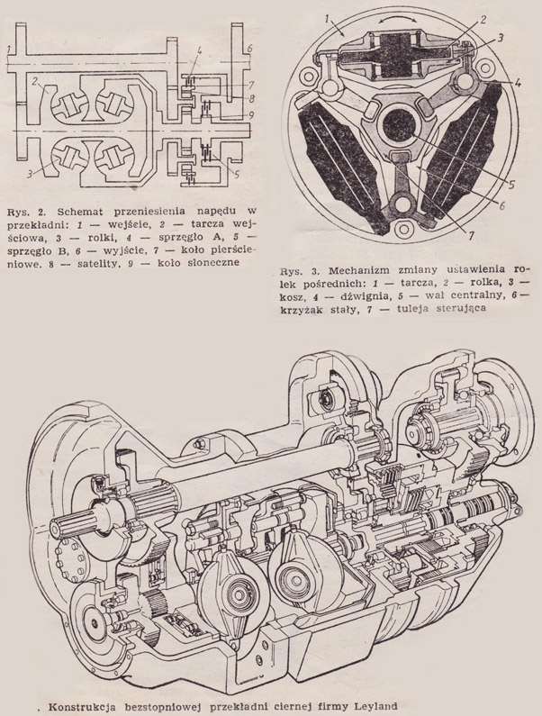
The continuously variable friction gear includes a pair of discs with a diameter 300 mm mounted on the input shaft and a double-sided output disc located between the input discs. Between the toroidal recesses of the outer discs and the inner disc, there are three intermediate rollers with a diameter 140 mm. The simultaneous deflection of these rollers causes the points of their contact with the inner and outer discs to change, and thus the change of the drive ratio. The position of the intermediate rollers is controlled by a slight rotary movement of the central adjustment sleeve. This movement causes the simultaneous angular deflection of the levers and the linear displacement of the roller baskets. This lateral shift of the contact points of the rollers with the discs causes the rollers to set themselves at a different angle and change the drive ratio.. A certain radial play in the seat of the adjusting sleeve on the axle ensures an even distribution of the transmitted power to all idler rollers of the transmission. A serious problem in this type of transmission is to ensure adequate pressure of the rollers to the discs. In the described solution this is achieved by means of a hydraulic cylinder exerting an axial force to 150 kN and pressures at the contact points up to 2300 MPa. Destruction of the raceway at such pressures is prevented by the use of special lubricating oils with high lubricity, which create an oil wedge separating the mating surfaces. At the same time, this wedge allows a slight slip to dampen the pulsations of the torque.
Regarding the fact, that the friction gear has no possibility to run idle or change the direction of rotation, it is connected in a bypass system with a planetary gear equipped with two clutches. The input of the friction gear and the satellite basket of the planetary gear are permanently meshed with the main shaft of the gear, and the output of the friction gear drives the sun gear of the planetary gear. When starting, clutch A connects the ring gear of the planetary gear to the output shaft, and clutch B is disengaged. When the rollers are parallel to the axis, they give the ratio of the friction gear 1:1, no torque is transmitted to the output shaft, for the sun wheel and the basket of satellites rotate at the same speeds in opposite directions. By reducing the ratio of the friction gear, the rotational speed of the sun gear is reduced, as a result, a torque appears on the ring wheel which is transmitted to the output shaft. Likewise, by increasing the gear ratio, we obtain a reverse gear. The range of gears achieved continuously with this type of work is 4,23 :1. At a speed corresponding to the second gear ratio of a conventional gear, the sun and ring gears of the planetary gear rotate in the same direction at equal speeds.. At this point, it switches to the second operating mode: clutch B is engaged, while clutch A is disengaged. From now on, the planetary gear is bypassed and the drive passes only through the friction gear, which enables high overdrive to be achieved 0,55 :1.
Gear ratio change, switching ranges and axial pressure in the friction gear are regulated by a hydraulic system controlled by a microcomputer. Unlike a traditional automatic transmission, this type of transmission requires control, continuous. The system uses a 16-bit microprocessor with control software 8 Kb and 2 Kb of random access memory. The system also includes the necessary digital and analog inputs and outputs to connect it to the driver, vehicle engine and transmission mechanisms. The main element of the actuator system is an electro-hydraulic valve that regulates the pressure in the actuator pressing the rollers against the discs. In order to reduce surface wear and reduce friction losses, this pressure is regulated as a function of the momentary load of the gear.
Advantages of a continuously variable friction gear, especially in conjunction with a flywheel brake energy recovery system have made, that Leyland committed significant funds to the construction work.