Keihin II Carburetor Removal and Installation
The design and principle of operation of the Keihin I and Keihin II carburetors are similar to each other. The figure shows the carburetor mounting components.
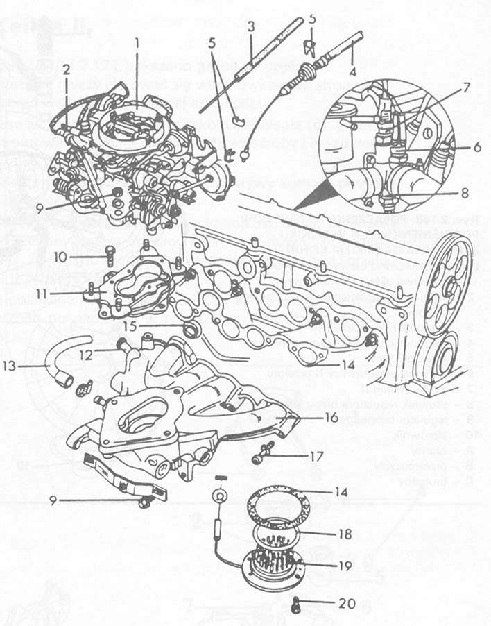
Lynx. KEIHIN II CARBURETOR MOUNTING DETAILS
1 – Keihin II carburetor
2 – fuel supply
3 – choke cable”
4 – throttle cable”
5 – vice
6 – heat switch of the intake manifold heater
7 – temperature sensor
8 – heat switch for speed controller
9 – nut 20 Nm
10 – screw 13 Nm
11 – carburetor flange
12 – servo vacuum hose connection
13 – cooling system pipe stub
14 – gasket
15 – gasket
16 – intake manifold
17 – screw 25 Nm
18 – o-ring”
19 – intake manifold heater
20 – screw 10 N m
■ Remove the air filter. Pay attention to where the cables are connected, to attach them during assembly in the same way as before disassembly. It is best to detach the cover from the largest wire (after loosening the buckle) and remove the filter element, then disconnect the other connections.
■ Disconnect the fuel supply and return pipes.
■ Disconnect the throttle cable” (4) throttle control. To do this, unscrew both nuts fastening the tie rod to the carburetor and remove from the socket. Pay attention to the ground cable below. Remove the throttle linkage. Do not remove the throttle cable guard.
■ Disconnect the choke control” (3).
■ Disconnect the vacuum lines from the starter and throttle actuators.
■ Disconnect the pneumatic ignition system control vacuum hose.
■ Disconnect the heater heat switch cable plug from the carburetor (heater) intake manifold (6).
■ Disconnect the temperature sensor cable plug (7).
■ Disconnect the plug for the heat switch (8) the idle speed control while coasting.
■ Unscrew the nuts and remove the carburetor.
■ Cover the hole in the intake manifold.
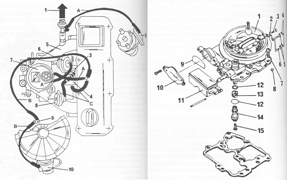
The carburetor is installed in the reverse order to removal. Replace the seals with new ones. Before installing, remove the remains of old gaskets from the sealing surfaces. When installing the air filter, pay attention to the correct installation of the hoses. The figure below shows the connection diagram of the vacuum lines according to their colors. Color marking of cables should minimize their incorrect installation. Finally, install the throttle and starter actuators.