Keihin I carburetor repair
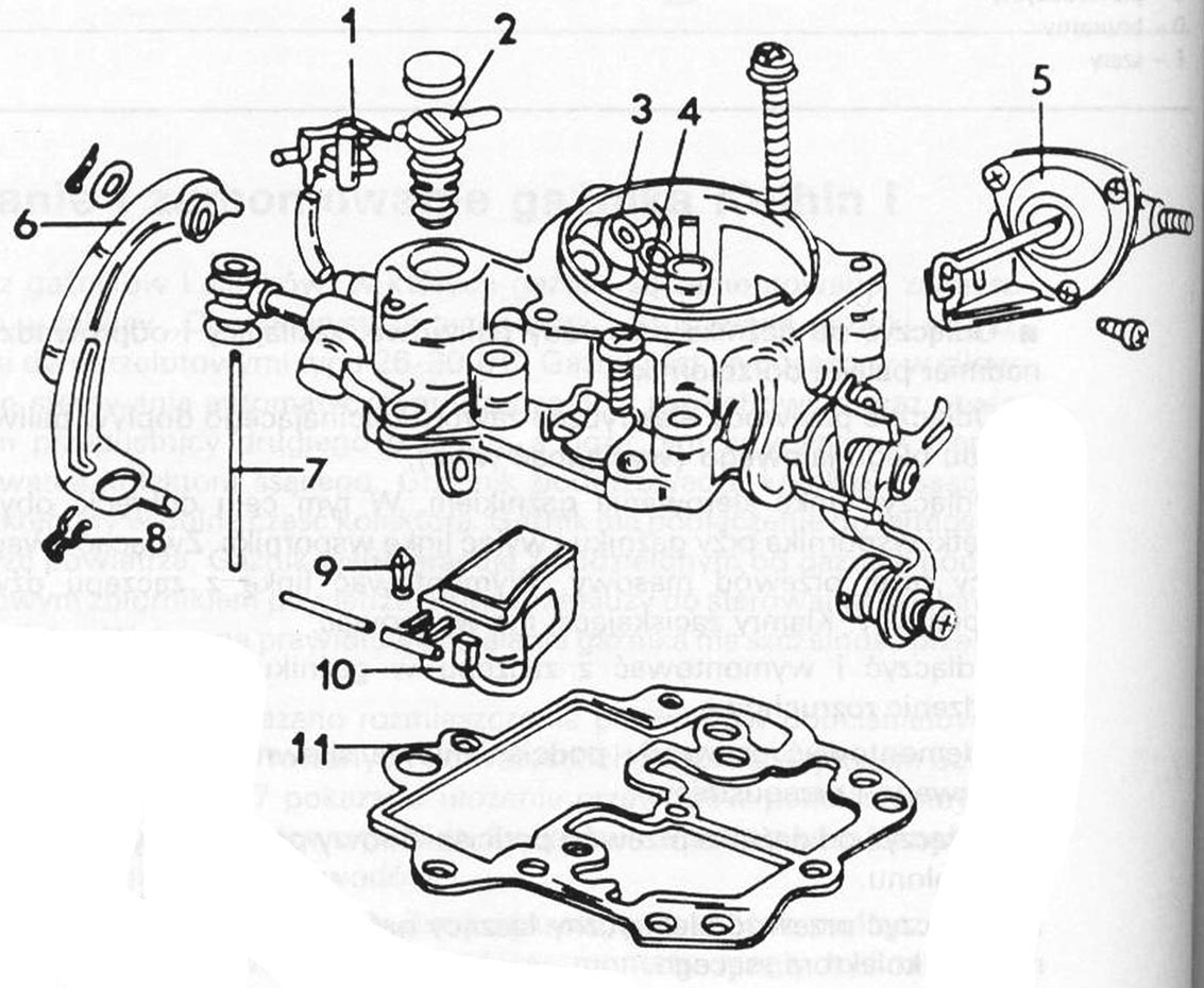 Drawing 1. KEIHIN I CARBURETOR ASSEMBLY DRAWING (carburetor cover)
1 – regulating valve
2 – suspension of the float valve needle
3 – carburetor cover
4 – carburetor cover bolt
5 – pull-down actuator”
6 – accelerator pump lever
7 – accelerator pump lever
8 – vice
9 – needle valve
10 – swimmer
11 – gasket (replace with a new one)
The figures show the parts of the carburetor, which should make disassembly and assembly much easier. Particular attention should be paid to the place of installation of individual nozzles.
Observe the following recommendations when repairing.
■ Never use wires or needles to clean the nozzles, because it always leads to the recalibration of the holes.
■ By replacing the nozzles, new nozzles of these dimensions must always be installed, which they had removed. Nozzles are selected separately for each type of engine. Replacing with nozzles of different sizes does not increase the power, acceleration improvements etc..
■ Only install parts supplied by Audi or the carburetor manufacturer in the carburetor.
■ Do not clean aluminum parts with sharp, hard objects. By tightening the screws, do not use excessive force and, above all, pay attention to the freedom of rotation of bolts and nuts in threaded elements. The threads in the aluminum parts are easily damaged, and imperfectly sealed parts are very often the cause of false air being sucked in, which has a negative effect on the operation of the engine, especially in the idle speed range.
■ Always use well-sharpened screwdrivers to unscrew the nozzles. The notches in the nozzle heads must not be damaged, as it cannot be ruled out that the nozzle opening is clogged or damaged.
■ When removing the float, avoid deforming the adjustment tabs, which, as a rule, leads to a change in the fuel level in the float chamber. The float should be protected against damage during storage. The tightness of the valve is checked, by blowing air into the valve after pressing the valve needle into the seat. During the test, the blown air should not pass through the valve. After removing pressure on the needle, air should flow freely through the valve.
 Lynx. 2. KEIHIN I CARBURETOR ASSEMBLY DRAWING (main body)
1 – II passage air nozzle,
2 – emulsion tube of passage II,
3 – air and passage nozzle,
4 – 1st passage emulsion tube,
5 – enrichment valve,
6 – plug,
7 – idle fuel nozzle,
8 – idle air nozzle,
9 – main jet of passage II,
10 – main jet I of the passage,
11 – mounting plate,
12 – II cruise throttle actuator,
13 – carburetor body,
14 – throttle advance actuator on vehicles with a manual gearbox,
15 – accelerator pump diaphragm,
16 – bumper for adjusting the pump flow,
17 – fuel shut-off valve to idle system,
18 – screw,
19 – idle adjustment screw,
20 – CO concentration adjustment screw.
21 – seal,
22 Idle speed adjustment screw for vehicles with a manual gearbox.
The carburetor is disassembled in the following order.
■ Dismantle the lever cable spring clip on the cover. Remove the tendon and remove all parts from the tendon. Unscrew and remove the screws securing the cover and remove the cover with the gasket. The long bolt inside the carburetor is secured with a fold-away washer. Replace the gasket with a new one.
■ Unscrew the needle valve from the cover.
■ Pull the split pins out of the rods of both diaphragms. Remove the washers. Unscrew both actuators.
■ Remove the nozzles shown in the figure 3. Idle fuel nozzle (7) is located under the cap, both emulsion tubes are located under the air nozzles (3) i (4). These tubes must not be changed when installing the carburetor.
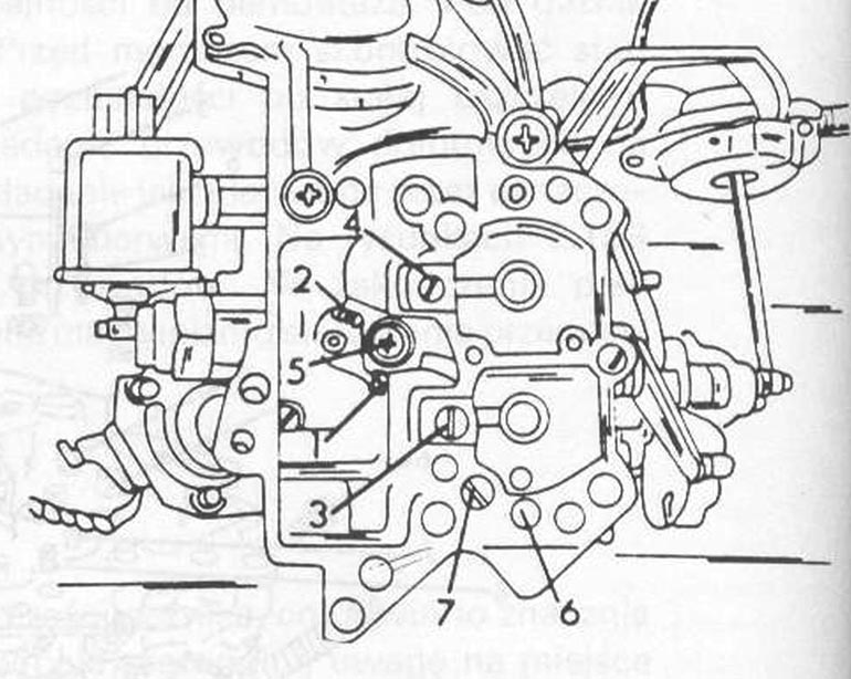 Fig. 3. LOCATION OF NOZZLES IN KEIHIN CARBURETOR I
1 – main jet I of the passage
2 – main jet of passage II
3 – air and passage nozzle
4 – II passage air nozzle
5 – enrichment valve
6 – idle air nozzle
7 – idle fuel nozzle (covered with a blanking plug)
■ Unscrew the accelerator pump from the bottom of the carburetor.
■ Remove the cap from the carbon monoxide adjusting screw. Remove the screw with the spring.
■ Remove the float axle together with the float. If the float needs to be replaced, pay attention to its type.
The carburetor is installed in the reverse order of disassembly. Be sure to follow the additional recommendations below.
■ If the accelerator pump has been removed, it must be reassembled according to the sequence shown in the assembly drawing. Pay attention to the correct installation of the carburetor cover.
■ Adjust after installing the pump which accelerates the injection of fuel.
■ Adjust the start throttle deflection.
■ If the enrichment tube is removed, replace the gasket with a new one.
■ Place the emulsion tube with the top outlet openings in the well and the passage, while an emulsion tube with bottom outlet openings to the second passage well. Please pay attention, so as not to swap the emulsion tubes.
■ The main nozzles vary in size and the illustration shows where to install them. The nozzle "bigger” located in the hole (2).
■ When tightening the carburetor cover bolts, secure the long bolt, bending the washer.
■ Remove the screw (a) so, that there is a gap between the bolt and the bumper.
■ Screw in the screw (a), until the gap is almost completely closed (check the width of the slit with cigarette paper).
■ Remove the screw (a) O 1/4 trading.
■ Secure the screw against unscrewing with a drop of varnish.
■ Adjust idle speed and CO concentration in exhaust gas.