The simplest gas installation, the so-called. we can install the first generation in cars, which are equipped with a carburetor power system. Currently, the most commonly used second-generation installations are intended for cars with engines powered by injection systems. The third generation of LPG installations, uses the multi-point power supply technique. Due to the popularity of second-generation gas installations, we will use an example of this when describing the construction.
An important element of the installation is the liquefied propane-butane tank. Made of steel sheet, usually cylindrical or toroidal in shape, may have different capacities, depending on the fuel demand of the vehicle and the amount of space available for its development. The tank is equipped with a mounting flange – Hello, to which the multivalve is screwed, fulfilling several tasks. Firstly, is an element, which allows you to fill the tank. It takes place using the filling valve, equipped with a non-return valve, connected to the multivalve with a copper pipe (in a typical diameter installation 8 mm). The multi-valve itself also has a check valve and protection, making it impossible to refuel with more LPG than 80% tank volume. Manual valves are installed at both outlets, enabling the LPG flow to be cut off in the event of failure of any of the pipes or in the event of their need to disassemble (np. sheet metal repair). The multivalve is connected to the reducer-evaporator by a copper pipe (6 mm), maximum working pressure, how can this cable withstand? 4,5 MPa. The power supply cable of the reducer should be fastened to the body maximally 0,7 m and can not run closer than 0,1 m from the exhaust system components. Compensation loops are often made on the conductors, protecting them against length changes, from temperature differences and against vibrations. Before the reducer, a gas solenoid valve is installed on the high pressure line, shut-off LPG outflow, when the car is running on petrol or the engine is not running. A pressure gauge is placed on the multivalve, fuel level in the tank to be read, the amount of remaining fuel is also signaled by appropriate LEDs, located next to the fuel type switch.
Diagram of a propane-butane supply system with multi-point gas injection (third generation)
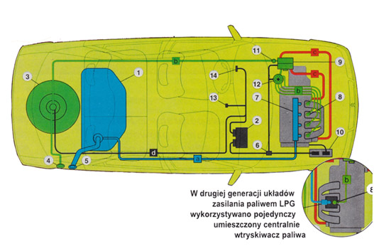
1 – Gasoline tank
2 – Electronic system that controls the operation of LPG installations
3 – Gas fuel tank. Two types of tanks are used: toroidal mounted in the spare wheel well; cylindrical placed along or across the trunk
4 – LPG fuel filler. The tank is filled with a special tip, ensuring the tightness of the system
5 – Gasoline filler
6 – Data relay between engine and LPG system controllers
7 – Gasoline injection system
8 – LPG fuel injectors
9 – Reducer-evaporator that converts liquid LPG fuel into gas fed to the injectors
10 – Engine management system for petrol fueling
11 – Valve that cuts off the gas supply to the reducer
12 – LPG fuel distributor for individual injectors
13 – Switch of the type of fuel supplied to the engine (petrol / gas)
14 – Gas fuel level indicator in the tank