Battery, inverter, distribution panel and wiring:
 I bought this one 1500 Coleman watt inverter, to power a few things, such as a cappuccino maker and a microwave oven. I was going to power the refrigerator and electronics from separate smaller inverters. However, before I started wiring, i wanted real performance values. I bought this one 1500 Coleman watt inverter, to power a few things, such as a cappuccino maker and a microwave oven. I was going to power the refrigerator and electronics from separate smaller inverters. However, before I started wiring, i wanted real performance values.
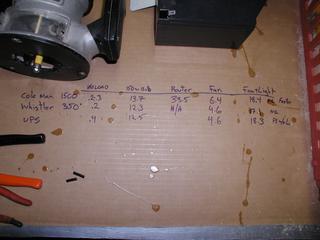
I set up a shunt to measure the current on the side 12 V and tried a large Coleman, 350-Whistler watt inverter and computer UPS with several different loads. I found a difference in the current draw, but it was smaller than I thought, that will be. In addition, all charges performed much better on the Coleman. The fan and bulb hummed slightly from all sources, but they were the least buzzing on the Coleman. |
|
 Surprisingly, the UPS computer was the dirtiest. Both a light bulb, as well as the fan buzzed a lot on the UPS. The fan wouldn't even run at full speed, if the resistive load of the bulb was not in parallel with it. Whistler performed better than the UPS, but Coleman ran the fan quietly and with no speed variation. Surprisingly, the UPS computer was the dirtiest. Both a light bulb, as well as the fan buzzed a lot on the UPS. The fan wouldn't even run at full speed, if the resistive load of the bulb was not in parallel with it. Whistler performed better than the UPS, but Coleman ran the fan quietly and with no speed variation.
So I think, that I will try to simplify it and give up other inverters. However, I will be using a UPS or two in-line to carry the load of some devices while transferring to and from shore power, to prevent the annoying flashing of “12:00”. |
Data: Light bulb without load 150 W Fan Fan and Router Light Bulb
Coleman 1500 0,2-0,3 13,7 6,4 18,4 33,6
Whistler 350,2 12,3 4,6 17,1 not applicable
UPS 0,4 12,5 4,6 18,3 not applicable
 Those EPIs from the dump fit the windshield quite nicely, they sound nice too. The receiver is from a roadside bin and only needed a little contact cleaner. Works nicely with the Coleman inverter. Those EPIs from the dump fit the windshield quite nicely, they sound nice too. The receiver is from a roadside bin and only needed a little contact cleaner. Works nicely with the Coleman inverter. |
|
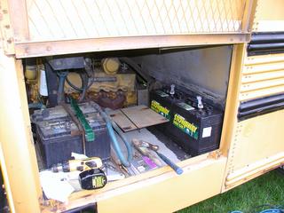 You want, keep house batteries as close as possible to the alternator. Looks like it, that my two golf cart batteries will fit in front of the air filter. You want, keep house batteries as close as possible to the alternator. Looks like it, that my two golf cart batteries will fit in front of the air filter. |
|
 I made the bracket holding the batteries out of the bed angle. Every week I bring home at least one bed frame from the Dumpster, I use them for everything. Seems, that they are available in sizes 1 “i 1 1/4”. Remember, to anneal them before drilling, if you don't, you will wear out drill bits quickly. I made the bracket holding the batteries out of the bed angle. Every week I bring home at least one bed frame from the Dumpster, I use them for everything. Seems, that they are available in sizes 1 “i 1 1/4”. Remember, to anneal them before drilling, if you don't, you will wear out drill bits quickly. |
|
 The battery tray extends out of the frame rail, so i installed this rod, to help support the outer edge. Because this rod connects the body to the frame, put a pair of rubber sleeves on the shelf. The battery tray extends out of the frame rail, so i installed this rod, to help support the outer edge. Because this rod connects the body to the frame, put a pair of rubber sleeves on the shelf. |
|
 Batteries are inserted, it is very tight fit, the air filter must be removed, to insert and remove the batteries. Batteries are inserted, it is very tight fit, the air filter must be removed, to insert and remove the batteries. |
|
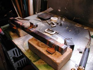
 None of the battery isolators at my local Timbuckt RV store were big enough, to service my alternator 150 A, so i bought this switch (250 A), not really sure, how will I use it. The cables are from a friend, who works at Cisco, were cut a little too short to the wardrobe, to which they were going, and my friend saved them for me from the garbage can. They've been sitting in my garage for over five years. None of the battery isolators at my local Timbuckt RV store were big enough, to service my alternator 150 A, so i bought this switch (250 A), not really sure, how will I use it. The cables are from a friend, who works at Cisco, were cut a little too short to the wardrobe, to which they were going, and my friend saved them for me from the garbage can. They've been sitting in my garage for over five years.
The third ear will connect to the battery charger. |
|
Switch mounted. |
|
 The switch will actually work rather well. The switch will actually work rather well.
|
|
 After much thought, I decided to place the electrical panels on several boards, just like at home. I realized, where in the engine compartment I have enough space and I cut and primed a few pieces of plywood 3/4 “. After much thought, I decided to place the electrical panels on several boards, just like at home. I realized, where in the engine compartment I have enough space and I cut and primed a few pieces of plywood 3/4 “. |
|
 Here is the finished DC board. The wire that powers the inverter is a cable 4/6 SOA, I connected the red and white and black and green wires, to obtain the equivalent current carrying capacity of the AWG conductor 4, what the inverter asked for. The fuse block has a value 100 amps, So 6 AWG was sufficient. Here is the finished DC board. The wire that powers the inverter is a cable 4/6 SOA, I connected the red and white and black and green wires, to obtain the equivalent current carrying capacity of the AWG conductor 4, what the inverter asked for. The fuse block has a value 100 amps, So 6 AWG was sufficient. |
|
 Here is the finished AC board. The panel is a box for 2 bearer, which I found in a dumpster near work, and the circuit breakers are GFI 2-gang circuit breaker 20 AMP, I bought by accident a few years ago, thinking, it's a single gang. Sharp eyes will not allow, so that the quad on the right includes a switchable outlet, it will be for battery charger, which output will be connected to the large battery switch 250. Here is the finished AC board. The panel is a box for 2 bearer, which I found in a dumpster near work, and the circuit breakers are GFI 2-gang circuit breaker 20 AMP, I bought by accident a few years ago, thinking, it's a single gang. Sharp eyes will not allow, so that the quad on the right includes a switchable outlet, it will be for battery charger, which output will be connected to the large battery switch 250. |
|
Here is another view of the dough holder, which I made from old bed frames. |
|
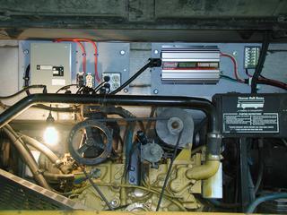 Ready boards mounted in the engine compartment. I was thinking about the heat from the motor acting on the inverter. However, while the engine is running, the fan pulls a stiff wind through the grille. Only after the engine has stopped, high temperatures are likely to occur in the upper part of the engine compartment. The inverter also has its own fan. We'll see, how it will end. Ready boards mounted in the engine compartment. I was thinking about the heat from the motor acting on the inverter. However, while the engine is running, the fan pulls a stiff wind through the grille. Only after the engine has stopped, high temperatures are likely to occur in the upper part of the engine compartment. The inverter also has its own fan. We'll see, how it will end.
In the photo you can see, that the AC box is connected to the inverter with an adapter 30-20 AMP. It is an "internally powered" mode for traveling and camping without external power. When AC will be available, I'll just plug it into a 20m extension cord 10/3 SOA, which i did. |
|
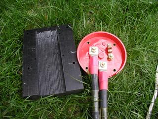
 Here is the battery charger installed. It is connected to a switched outlet on the AC side and connected to the battery disconnect switch 250 And on the DC side. I originally purchased a "smart" charger to be installed here. However, when I tried it, I found it, that the RFI from the switching power supply interfered with radio reception to an unacceptable degree. The Smart charger now lives in my garage, and this old transformer charger will travel with the bus. Here is the battery charger installed. It is connected to a switched outlet on the AC side and connected to the battery disconnect switch 250 And on the DC side. I originally purchased a "smart" charger to be installed here. However, when I tried it, I found it, that the RFI from the switching power supply interfered with radio reception to an unacceptable degree. The Smart charger now lives in my garage, and this old transformer charger will travel with the bus. |
|
 Internal cabling will typically run in the cabling channel above the windows. There is plenty of room on both sides for several cables. The wire will run along the side of the bus in the wireways, like this product from Home Depot. This circuit will be designed for small kitchen appliances. Internal cabling will typically run in the cabling channel above the windows. There is plenty of room on both sides for several cables. The wire will run along the side of the bus in the wireways, like this product from Home Depot. This circuit will be designed for small kitchen appliances. |
|
 I opted for brown Bakelite switches and sockets with solid brass plates, to give the appearance of things from the beginning of the 20th century. I opted for brown Bakelite switches and sockets with solid brass plates, to give the appearance of things from the beginning of the 20th century. |